Posts

Showing posts from 2021

Secrets of the YM2154

Image
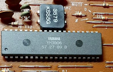
  After a break, I returned to the PSR-70 reverse engineering project: t he YM2154, a.k.a. RYP4 is still an unknown territory. The time has come to reveal its secrets. R YP4 is used a bit more widely than OPQ. Besides PSR-60/70 it is used at least in PSR-80 and RX- 11/15/21 drum machines. This time I did remember to check for service manuals, and found one for RX-11: https://elektrotanya.com/yamaha_rx11_sm.pdf/download.html . This contains a full schematic and other useful information.   T racing register writes Because I had good results with OPQ by tracing what the PSR-70 firmware is writing to the chip registers, this would be a good starting point also for RYP4. The chip has 128 registers which reside in Z80 I/O address space at addresses 80H...FFH. Looking at the disassembly listing reveals quickly that there is no single function which would take care of all the register writes, like OPQ had. There are many IN and OUT instructions accessing the RYP4 register

Digging into YM3806

Image
In the previous post I got the PSR-70 original firmware modified so that it dumps to serial port all register writes done to OPQ chip (YM3806). Now I’m getting the data I wanted and plenty of it! A simple keyboard key-down or key-up produce only under 20 register writes but changing sound from the front panel results in about 300 writes. Why 300, there are only 256 registers? Yes, but there are many registers which are written several times. T he raw dumps from the modified firmware are quite hard to read, they just list the register address and written value in hex in the order they happened: 1F=20 5E=1F 56=1F 4E=20 46=20 5E=81 56=81 4E=81 46=81 9E=1F … To make some sense out of this I wrote a small python script to analyze the dump. It lists all registers in numerical order and all writes done to that register. In the script output the first column is OPQ register number, second column is the number of writes to that register and then a list of the written values.

Reversing the PSR-70 firmware

Image
Now that we know enough of the PSR-70 hardware , it is time to start studying the firmware. It resides in one 32 KB EPROM, which is inconveniently soldered directly on the circuit board without any socket. Luckily the board is single-sided, so it was quite an easy task to remove it using a proper desoldering station. After this I soldered a socket in place of the EPROM. I have an old Stag EPROM programmer, so no problem in reading the EPROM. I programmed the contents in another EPROM and inserted it in the socket. The keyboard worked without problems with the copy, so the reading was successful. I have sometimes got incorrect reading results, so it is always worth checking. Stag can dump the EPROM contents in intel-hex format, which I disassembled with yazd . This is quite nice Z80 disassembler, it produces good cross-references, which help analyzing the software. Hex and disassembly listings are in my Github . Analyzing the disassembly Target is not to understand

Reversing the PSR-70 hardware

Image
  First step in the actual reverse engineering is to start studying the PSR-70 hardware. This is quite service-friendly (meaning hacker-friendly) device: all circuit boards are single-sided and copper side silkscreen has IC numbers and jumper wire positions marked. There are also many useful looking signal names marked, like “D7”, “A12”, “IOWR” etc. It would be possible to draw the whole schematic from one high-quality photo of the circuit board. My intention is not to draw the whole schematic, but at least the address maps should be figured out. It will make the interpretation of disassembly much easier. All address decoding is done with 7400-series discrete logic, no PAL-circuits or other nuisances used, this is very good.   Block diagram Most of the electronics is on the large main board . The other cards are: Power + audio board contains the audio amplifiers, some kind of analog chorus-effect based on a BBD-circuit, power amplifiers feeding the speakers, and voltage