Posts

Showing posts from 2020

Wiring it up

Image
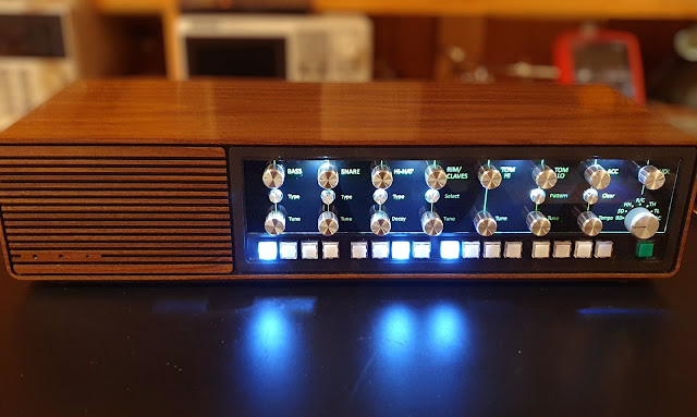
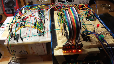
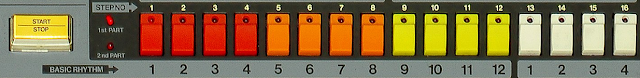
The drum machine project is getting near the end. It still needs to be put mechanically together and do the wiring. Although I have designed the system, it still came a bit as a surprise how much wiring there actually is. I found myself drawing wiring diagrams page after page. Wiring of this complexity level cannot be done without proper diagrams, at least I cannot plan and solder at the same time. The parts that need to be interconnected: 8 circuit boards upper front panel (part of the chassis) 15 pots, part of them tandem 6 push switches a 7-position rotary switch lower front panel (part of the housing) 16 sequencer buttons, with leds 1 start/stop button, with led connectors at the back line out external sync speaker One of my many hand-drawn diagrams, the trigger wiring. I won’t put them all here, the re are too many of them , and part of them are not easy to understand for anyone else.   Here is the chassis built up, sound control pots and push swit

From radio case to drum machine case

Image
In the previous post I found the N ordmende radio for housing of the drum machine. It looks like promising starting point for the enclosure, but it will need all kinds mechanical work before it suits to purpose. When buying the radio, I was hoping the case would have been wood, but it is not, it’s plastic. Everything is a single piece, only the back panel is separate. This does not make fitting the new electronics a ny easier. T he idea is to attach the sequencer buttons in the lower part of the front panel, where the radio buttons and volume and tone controls have been. All control knobs and switches are located in the upper part of the front panel, where the radio’s frequency scale and dial have been . Because the cast housing has quite complex forms, I modeled it partially in Fusion 360 to get better understanding how to fit the mechanical parts. The sequencer buttons from eBay fit just nicely to the slot in the lower front panel, but there is one problem: ther

Housing and power supply

Image
Now all circuit boards of the drum machine are finally ready and it is time to start thinking what kind of housing would be suitable for the project. As the sounds and electronics are heavily 70’s oriented, the casing should also be . I ha d a vision that a radio from the 70’s might be good for this, preferably a tabletop model which has enough space for the circuit boards and everything . They have always an internal speaker which is handy for using the drum machine in a “stand-alone mode”. Searching the internet again, this time various flea markets and other sites selling old junk. After a while I found a neat looking Nordmende Fidelio tabletop radio from late 70’s. It did not cost much and was in very good condition from outside. It did work also as a radio, but I was not very interested about that, because the original electronics will be removed anyway. Radio internals look like this: The large amount of acoustic cushion material was a bit disappointing, it

Sequencer to PCBs

Image
Now the necessary changes to original sequencer have been done and tested on breadboard, so it is time to start designing the printed circuit board(s). The sequencer uses mostly standard 7400- and 4000-series ICs. They are not very hard to get, I have many of them in my own stock, and local Hacklab has good supply of vintage components. The 74C922 keyboard encoder is a bit more rare, I ordered it from eBay. And soon after that Hacklab got a nother component donation, including bunch of 74C922s. Such is life. Other than that, there are couple of 555, ULN2003 and the RAM, which I already mentioned in a previous post. No thing exotic . As previously said I’m using Eagle free version for designing PCBs. It has some limitations but they are not that bad as they look. The sequencer contains 24 ICs, so there is no hope in fit ting them to one 8*10 cm board. But two boards might be feasible, it is only 12 ICs per board. When stacking those with spacers, the stack will be much

Changes to sequencer

Image
  Although Matt Sarnoff’s design is a very good starting point for my drum machine's sequencer , it will need some changes. Now it is again time to grab the breadboard and start testing the changes. Memory The o riginal sequencer uses 74LS189 as the memory chip. It is a 4*16 bit memory which dictates that the sequencer has 4 channels. Since I need 7 channels, something must be done. An e asy way would be to use two 74LS189s in parallel. But I would like to have a non-volatile pattern memory, and also space for more than one patterns. Then the LS189 starts to be problematic. Actually the whole idea about a non-volatile pattern memory occurred to me when I found couple of Mostek MK48Z02 ZeroPower RAM ICs from my junk collection. It is a static RAM with integrated lithium battery, made in the 80’s. It acts otherwise as a normal static RAM chip but if you cut the power, it will retain its contents using the integrated battery. Although m anufacturer promises 10 years li

Getting things sequenced

Image
So far my analog drum machine project has concentrated heavily on the sound generation. While this is admittedly the most important part of the machine, the generators will not generate a single sound without trigger pulses. That’s why each drum machine contains some kind of sequencer. And this is what we’ll concentrate on next. I used Arduino and a modified version of Jan Östman’s O2_minipops software as a sequencer during the sound generator testing. But this is not the way I’m going to go with the actual project. I don’t normally use Arduino in my projects. It is good for quick tests and hacks, but for a “real” project, preferably something else. From the very beginning of this project I have had a vision that the sequencer user interface should be similar to TR-808: sixteen buttons in a row with l ight s, showing steps of one channel at a time; changing the step status by pressing the corresponding button; rotary switch to select the active channel; o ne button to

Sound generators to PCBs

Image
Next phase in the analog drums project would be to design printed circuit boards for the sound generators. This will again need some planning. I’m using the free version of Eagle as my PCB CAD, and it has some limitations. The biggest of those are: only two layers and board maximum size 8*10 cm. Two layers is almost never a problem in my projects . Some people consider the board size as a big limitation, but it is not always that straightforward. If you find yourself in a need of bigger board, ask yourself: did my hardware modularization go as it should have? This limitation forces you to think your hardware as reasonable sized modules, and it is never a bad thing. Of course, there are situations when the PCB must be just certain size, but most of the time, this limitation is not a big deal. Considering that t he generators, mixers and others consist of 19 op amps, 13 transistors and something like 300 passive components, they surely won’t fit on an 8*10 cm board. So m

Mixing it together

Image
In the analog drums project, altogether 10 sound generators have now been breadboarded and tested. I think now it is time to stop collecting various nice sounding generators and start to figure out how these will be used together. After some thinking and wondering, I came up with the overall structure of the drum machine like this. Here I’m assuming that all 10 sound generators are in use:       Basic principles: N oise generator is common to all sound generators needing noise. Sequencer has as many trigger channels as there are sound generators + 1 for accent. Each sound generator has two outputs: one for normal sound and one for accent. Each sound main output goes to main mixer through channel’s own level control. Each generator’s accent output goes to accent mixer. The mixed accent signal goes to accenter circuit and from there to main mixer through the accent level control. Main output level control is after the main mixer. The accent output in the sound gen