Housing and power supply
Now all circuit boards of the drum machine are finally ready and it is time to start thinking what kind of housing would be suitable for the project. As the sounds and electronics are heavily 70’s oriented, the casing should also be. I had a vision that a radio from the 70’s might be good for this, preferably a tabletop model which has enough space for the circuit boards and everything. They have always an internal speaker which is handy for using the drum machine in a “stand-alone mode”.
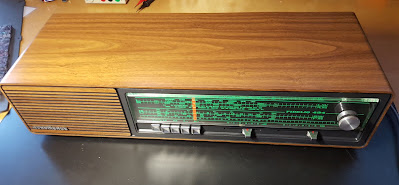
Searching the internet again, this time various flea markets and other sites selling old junk. After a while I found a neat looking Nordmende Fidelio tabletop radio from late 70’s. It did not cost much and was in very good condition from outside. It did work also as a radio, but I was not very interested about that, because the original electronics will be removed anyway.
Radio internals look like this:
The large amount of acoustic cushion material was a bit disappointing, it will make fitting the new electronics more difficult. Of course parts of it can and must be removed, but it is there on purpose. They have had some resonance problems with the enclosure, so it is best to leave most of the padding there.
Here is the original electronics removed from the radio. The audio amplifier and the power supply with mains transformer look like they could be re-used in the project. Amplifier and power are anyway needed for the drum machine in some form or another. This amplifier uses AC187/188 pair in the output stage, so it is very authentic 70’s!
I found the schematics of the radio at radiomuseum.org. Here are the essential parts related to this project.
Now it would be a good time to decide about the power supply. This kind of quite complex pile of analog and digital electronics is often very sensitive to all kinds of interference. A properly designed power supply can help a lot. A good principle is to use separate, floating supplies for each part.
Using the radio’s original power supply might help in this. Its mains transformer has two separate secondary windings. One is feeding the audio amplifier (and the rest of the radio, which will not be used), the other is feeding only the frequency scale lamp, which will not be used either. So here is a free winding, producing about 13 VAC. There is a 200 mA fuse in the lamp circuit, so at least that current it should be able to produce.
I don’t like the idea to supply both analog and digital circuitry from the same supply, it will most probably lead to problems with mysterious noises and hums. It might be beneficial to use yet another transformer to feed the digital side (the sequencer).
In my never failing junk box I happened to have a small mains transformer with 2x12V outputs. This may be suitable. After this I will have a triple power supply:
- Nordmende’s transformer feeds the radio’s original audio amplifier
- Nordmende’s transformer lamp winding feeds the sound generators
- Extra transformer feeds the sequencers
When all supplies are floating in respect to each other, the connection of the grounds can be done in optimal places to minimize the hums. Non-floating supplies would give much less possibilities in this regard.
I
built a small auxiliary power
board containing the extra transformer with rectifier and filtering,
and another rectifier + filtering for the lamp winding. This is so
simple I did not mind doing any PCB for it, I used only Veroboard.
This is how the board looks, already installed in the chassis:
In the next post it is time to start working with the radio enclosure to get all the electronics fitted in.


Comments
Post a Comment